1 inch ss ball valve
gate valve butterfly valve
api valve trim chart
gear operated valve
The role of control valves in the industrial process loop is becoming increasingly important. As a reliable control valve manufacturer, we would like to introduce the different types of control valves, components, functions, application scenarios, and valve accessories, in a systematic and professional way in this article.
What Is The Difference Between Pressure Control Valve and Flow Control Valve
Basic Introduction to Control Valves
In this section we are going to introduce a piece of brief information about control valves, in case help you to know what control valve is and which role has it played.
What is a Control Valve?
As industrial automation processes are upgraded, more and more control valves are being used in process circuits. Almost every plant consists of hundreds of control loops. All loops are in turn networked together and used to keep a number of important process variables within defined limits to ensure the quality of the final product. These parameters include pressure, flow, temperature, level, etc. The sensors and transmitters collect the process variables to the controller, after comparing with the desired setpoints, the controller sends a corrective signal to control valves, in case modulating the valve opening to reach the required value.
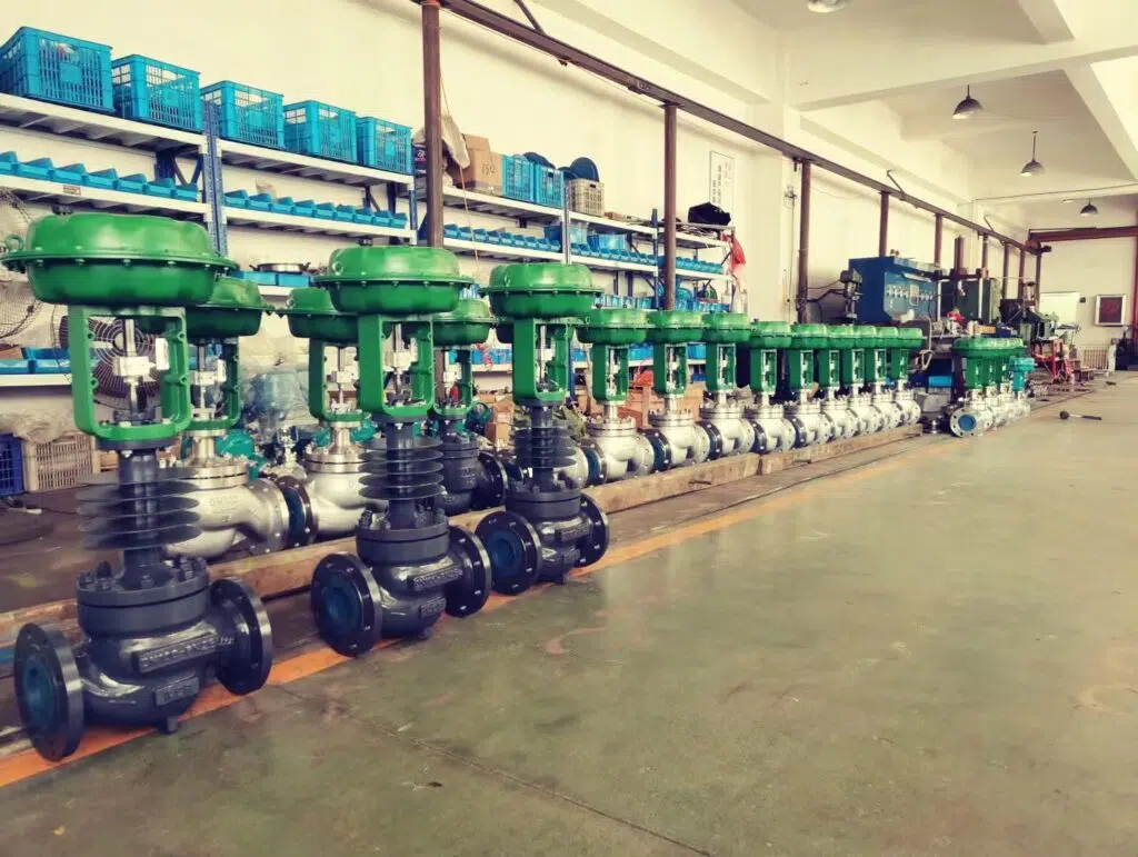
In brief, a control valve is a key part of a control loop, a critical control element in industry processes, which consists of a pneumatic actuator, electric actuator, or hydraulic actuator assembly with a valve for regulating the flow capacity or temperature of fluids, or upstream pressure and downstream pressure, or level. It is widely used in petroleum, chemical, pharmaceutical, textile, paper industry, refining, oil and gas, iron and steel metallurgy, and other industries.
Principles of Operation For Control Loop
By now we all know that the most common final control element in the process control industry is the control valve. The ultimate purpose of a control valve is to regulate the temperature, pressure, level or flow of a medium while compensating for load disturbances so that the process variable being regulated is as close to the set value as possible. The medium could be water, steam, oil, gas, or other compounds.
Typically, a control loop consists of a sensor that detects the process parameters, a transmitter, a control valve, and a controller.
The sensor and transmitter collect process variables in the loop and act as an eye to monitor changes in individual parameters such as the temperature, pressure, or level of the medium. The collected value is then sent to the controller. Through the controller, which functions like a brain, the “process variable” received by the transmitter is compared with the “set point” and a corrective signal is sent to the control valve. So the control valve, as the final control element, plays the role of the hand in the control loop, making it the most important part of the automatic control system.
Types of Control Valves
There are many types of control valves, each designed for specific types of applications, read this post for more details on different types of control valves.
Globe Type Control Valve
Globe type control valve is the most common final control element during the process loop, and it gets its name as its spherical shape. According to the ports of the globe valve body, it includes 2-way control, 3-way mixing control, and 3-way diverting type.
Butterfly Type(High Performance and Triple Offset)
When we talk about butterfly control valves, we generally refer to high-performance butterfly valves (double eccentric butterfly valves) and triple eccentric butterfly valves (triple offset butterfly valves).
In most applications, butterfly valves can replace other types of control valves because they provide the same basic functions, but often have more safety features and better performance. Using butterfly valves in your application can reduce maintenance requirements, improve the accuracy of flow control, and reduce the risk of disasters such as leakage. Butterfly control valves are also used to control water treatment plants because they provide the best seal and can withstand water pressure. Especially in large-diameter pipelines, the use of butterfly control valves is cost-effective.
V-Port or Segment Ball Valve
The v-port or segmented ball is the most common type for ball control valves. Ball valves are widely used in fluid systems in many industries due to their low cost, durability, and excellent closing performance. Similar to butterfly valves, they are not as effective in flow control applications that require high precision and control sensitivity. One of the reasons is that the ball valve requires high torque to open and close, which prevents the operator from making fine adjustments. There is also a certain gap between the stem and the ball, which makes it difficult to find a specific flow rate suitable for fluid control applications.
Eccentric Plug Control Valve
The eccentric rotary valve is an innovative technology that combines many of the ruggedness, compactness, and long-stem seal life of globe valves with simplicity and reliability.
The eccentric plug rotary control valves have two offset for construction design. One is the shaft is offset behind the valve seat and the other is the shaft is offset from the centerline of the valve.
When the valve shaft and plug of the eccentric plug control valve start to move, the plug cams away forward open from the seat once the valve just started. There is no friction between the plug and the seat.
Reduced Trim Full Ball Valve
The reduced trim full ball valve is the design that has a triangular window on side of the ball.
This reduced trim ball valve is not commonly used in initial selection and sizing, most applications are when you find after the plant starts up that a ball control valve is oversized, the capacity is way large than the process required, so if you are not able to alter the piping to accommodate the smaller size valve and the necessary piping reducers, then reduced trim full ball valve is your best choice.
Most of the flow path windows are triangular or V-shaped to get as close as possible to the inherent flow characteristics of EQ%. The wide width of the window determines the maximum flow capacity of the control valve.
Globe Control Valves vs. V-Port Ball Control Valves
| Item | Globe Type Control Valve | V-Port Ball Valve |
| Function | 2-Way Flow Control Valve 3-Way Mixing Type Control Valve 3-Way Diverting Type Control Valve | 2-Way Flow Control Valve |
| Shutoff Tightness | Not Zero Leakage | Positive Shutoff, Zero Leakage |
| Control Accuracy | Excellence | Coarse |
| High Response Cycle | Yes, Constant Control | No |
| Flow Capacity | Lower | Higher |
| Cavitation Prevention | Priority Selection | – |
| High Temperature | Priority Selection | – |
| Easy Maintenance | Priority Selection | – |
| Cost | – | More Economical Solution |
Component for Control Valves
There are two major types of control valves, linear and rotary motion. The rotary type control valve is a quarter-turn motion, and the linear type control valve is a sliding motion. So we will separate those two types and list each component for control valves.
Linear Motion Control Valve (Globe Type)
Above is a cross-sectional view of a globe type control valve, which clearly shows the main components. globe type control valves can also be called sliding globe type control valves.
- Valve body
The valve body is the main part of the control valve, which is the channel to carry the fluid pressure and control the variable parameters. The valve body is the main component of the control valve and is the channel that carries the fluid pressure and control variables. - Bonnet
The bonnet is the part of the valve that carries the pressure and keeps the valve body and stem sealed by the stem seal packing. As a globe type control valve, the bonnet is bolted to the valve body to facilitate the assembly of the valve internals. This type of bonnet is also known as a bolted bonnet design, as opposed to the integral cast bonnet of most rotary valves. - Trim
The valve trim generally consists of a stem, plug, and seat.
The stem is used to connect the actuator to the plug.
The plug is the movable element that is assembled in the flow path to change the flow of the medium through the valve.
The seat is fixed to the valve body and together with the plug forms the fluid passage while providing a contact surface for the plug to close the flow.
Rotary Motion Control Valve (Butterfly Type and Ball Type)
Rotary control valves are also known as quarter-turn control valves, and the definition of each part is similar to that of linear type control valves. Only the name of the bonnet is different. The bonnet of almost all rotary valves is cast as a part of the valve body as an entirety and is usually called an “integral bonnet”. Instead, the bonnet is bolted to the valve body as in the case of globe valves.
The part that connects the actuator to the closure element is called a stem by some manufacturers, and a shaft by others.
The closure element of a butterfly valve is called a disc, while a ball valve is called a sphere or ball.
Accessories
Actuator
The actuator for the control valve is a mechanical device that uses an external power to modulate valves.
There are four different types of actuators for the control valve, pneumatic actuator, electric actuator, hydraulic actuator, and self-operated actuator. An actuator is an important component for control valves, which drive to open or close valve. For the industrial process control loop, pneumatic and electric actuated are the most common types.
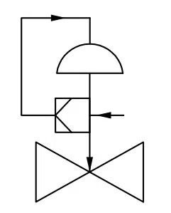
Pneumatic Actuator
The pneumatic actuator includes a multi-spring diaphragm pneumatic actuator, single-spring diaphragm pneumatic actuator, sing-acting and double-acting piston/cylinder pneumatic actuator, and rotary type pneumatic actuator(rack&pinion, and scotch yoke).
- Multi-Spring Diaphragm Pneumatic Actuator
The multi-spring membrane pneumatic actuators of spring return type are applied for control operation of control valves, and other positioning elements in industrial automatic systems. There are two following design options for the actuator:
- Direct action (air – advances the steam)
- Reverse action (air – retracts the steam)
(a) Direct-acting (PZMA)
- Upper diaphragm castings
- Diaphragm
- Diaphragm plate
- Spring
- Down diaphragm castings
- Actuator stem
- Yoke
- Adjust nut
- Travel indicator
(b) Reverse-acting (PZMB)
- Upper diaphragm castings
- Diaphragm
- Diaphragm plate
- Spring
- Down diaphragm castings
- Actuator stem
- Yoke
- Adjust nut
- Travel indicator
2. Single-Spring Diaphragm Pneumatic Actuator
3. Linear Piston/Cylinder Pneumatic Actuator
4. Rotary Type Pneumatic Actuator
How to select the right actuator for your application?
We know that an automated control valve needs an actuator to operate the valve, pneumatic actuator and electric actuator are different, so it may cause confusion when you select an actuator for your application. The following step-by-step method can help you figure out which actuator is exactly perfect for your condition.
Step 1: Check the valve type
Linear type control valve
Linear type control valve includes globe type, gate type, and pinch valve. The actuator assembly for these control valves must provide linear motion to operation.
Rotary type control valve
The rotary type control valve applies the actuator produces the rotational motion to operate a valve. Eccentric plug valve, butterfly valve, segment ball Valve, and full port ball valve are all categories by rotary type control valve.
Electric actuators have high levels of precision, control, and energy efficiency. They are usually used for on/off control with fail in the last valve position. And its cost is more expensive than pneumatic rotary actuators.
Pneumatic rotary actuators are known for fewer and simple components, so it makes easier and cheap for maintenance work. Pneumatic actuators with spring return are very commonly used for the failsafe condition, such as FC(fail to close valve) or FO(fail to open valve).
Step 2: Check the available power source on your site
This is a key issue if the site can only provide electric power, not equipped with external air source equipment, in order to save costs, generally use an electric control valve. On the contrary, if equipped with sufficient air supply, then pneumatic control valves are a better option for the process loop.
Pneumatic diaphragm actuators usually required an airpower range of 1.4 bar to 4.5 bar, and piston-type pneumatic actuators required 3 bar to 10 bar power. It’s difficult for plants to guarantee above 6bar at all times for the process equipment, it’s one of the reasons why diaphragm actuators are so commonly assembled for control valves. If low airpower which under 5 bar will require a large size of pistons to generate torque to operate valves.
Piston pneumatic actuators are available in two main types: rack&pinion, and scotch yoke.
Both of these rotary pneumatic actuator types provide a compact and economical solution for quarter-turn(90-degree) full port ball valves, eccentric plug control valves, high-performance butterfly valves, and segment ball valves.
In many plants, electric actuators are commonly available power voltages with 12 and 24 VDC, and 24, 120, and 220 VAC, 1-phase. For power plants, most use 380V, and 400V 3-phase power.
Step 3: Installation Space
Usually, in complex piping systems, we need to consider the installation space of the control valve, for the narrow installation space, the engineer needs to first consider the compact rotary type control valve, such as eccentric plug control valve, segment ball valve, and butterfly control valve.
Step 4: Function
Most engineering has requirements for actuator function, such as on/off or modulating, service cycle life, failure position, operating speed, control accuracy, assemble with manual operator/handwheel, local control, or others.
We also need to consider the media characteristics if it’s flammable, then pneumatic actuators are safer than electric actuators. So pneumatic actuators are very commonly used in hazardous or explosive working areas, however, any electrical accessories such as limit switch, valve positioner, and solenoid valve assemble for pneumatic actuator still need to meet NEMA standards.
The electric actuator also can be used in hazardous areas, just more expensive than the pneumatic actuator. Just need electrical components and enclosure to meet the NEMA standards.
Step 5: Environmental conditions or ambient temperature
General pneumatic actuators can handle temperature ranges between -4°F to 175°F, due to the piston seal ring, bearing, and mounting design can’t bear high temperatures.
Since low-temperature environments can cause air sources to condense, the condensate may freeze and block the air supply tube, causing the pneumatic actuator to fail to operate.
Electric actuators can be used in the temperature range of -40 to 150°F, but are also affected by ambient temperature and humidity. When used outdoors, electric actuators should be rated for that environment to prevent moisture buildup from damaging electrical components. Also in outdoor low-temperature environments, the heat from the motor can cause condensation to form on the electric actuator housing, so the actuator should be fitted with thermostat accessories or a heater to maintain a constant temperature and avoid the occurrence of condensation issues.
Step 6: Budget
In general, the cost for globe type control valve is higher than rotary type control valve, such as butterfly type and ball type.
Electric Actuator
The electrical actuator is mounted on the control valve which uses an electromagnetic device converts electrical energy into mechanical movement, it uses an external power source like 220VDC, 24VAC, 380V, or other power voltage to drive valves. Most electrical actuators use limit switches to turn the motor off when the actuator reaches the final valve position, due to it is activated by cams that are mounted on the stem drive shaft.
Electric actuators can be classified as linear and rotary electrical actuators.
The linear electrical actuator also called motorized valve actuator, which commonly used for globe type control valves. For rising stem control valves assemble electric actuators to operate with a screw drive. The closure element of the valve is moved up and down by the rotation of a threaded rod that is connected to the valve stem.
Valve Positioner
- Mechanical electro-pneumatic positioner
- Mechanical pneumatic-pneumatic positioner
- Digital valve positioner
- Smart valve positioner
Limit Switch
A limit switch for control valves is a device designed to provide a valve position signal to the controller, such as PLC or DCS control system. This accessory can be integral to an electrical actuator and be separately assembled into a pneumatic actuator or valve yoke.
Generally, there are two common types of limit switches used for control valves regarding valve movement.
For sliding stem/linear type control valve, these limit switches are assembled at the valve stem and enable the signal of valve opening or close position to the control system. Some conditions only require one signal of valve closing or opening to the controller, but some require both positions, valve close, and valve open position.
Two available options:
- 1PC limit switch assembly for linear type control valves, signaling valve close, or valve open position.
- 2PCS limit switches assembly for linear type control valves, signaling valve close, and valve open position.
For rotary type control valves, like ball valve, butterfly valve, and eccentric plug rotary control valve, they use a limit switches box, which has a visual indication of the valve position. The limit switches box is typically activated by cams connected to the shaft and equipped on the pneumatic actuator to the control valve.
Limit switches send electrical feedback from two micro switches to indicate valve position. Typically for on/off type control valve, which confirms either open or close position in site.
Solenoid Valve
Solenoid valve is equipped with pneumatic control globe valves that main function is to lock the valve at the last valve position, and also it can vent out the air from the pneumatic actuator, in case drive valve to the safe position.
Lockup Valve
I/P Transducers
I/P transducer means making a current signal 4-20mA converts proportional pressure output of 3-15psi. This accessory is used for an application that does not require a high level of positioner accuracy of a positioner, only needs an electro-pneumatic sensor to transfer the signal.
Air Filter Regulator
An air filter regulator is a necessary accessory for the control valve, usually assembly before the actuator, in case the air power reduces the right pressure range for the pneumatic actuator. For example, if the diaphragm pneumatic actuator requires 2.4bar air power, then we need to adjust the air filter regulator to reduce the pressure to meet 2.4bar, otherwise, the air power will damage the diaphragm. Also, it can filter the Impurities in the air.
Volume Booster
Volume booster is used for large volume needed pneumatic actuator, the airpower is not enough to provide large air volume in a short time, so in case of speed up the response of control valve, volume booster can provide extra pneumatic thrust output capacity to the valve.
Typically single-acting pneumatic actuators only request one volume booster, and double-acting pneumatic actuators require at least two sets.
Quick Exhaust Valve
Compressed air flows from the control valve and through the quick exhaust valve to the cylinder, speeding up the opening time of the valve.
Position Transmitter
Sometimes control valve required a positioner transmitter that can send a 4-20mA output signal to control system, in case to feedback a actual valve position.
Manual Operator
A manual operator is an additional handwheel for the control valve, in the case of an emergency situation we can operate by a manual operator.
There are three types of manual operators for control valves.
- Top-mounted handwheel (Usually for linear type pneumatic actuator)
- Side-mounted handwheel(Either linear or rotary type pneumatic actuator)
- Gear Operated handwheel (For rotary type control valves, such as ball, eccentric plug, or butterfly valves)
The Installation Layout of the Control Valve
Valve Types and Typical Applications
| Valve Type | Isolation | Modulating | Pressure Relief | Directional Change |
| Gate | R | × | × | × |
| Globe | R | R | × | R(note 1) |
| Check | (note 2) | × | × | × |
| Stop Check | R | × | × | × |
| Butterfly | R | R | × | × |
| Ball | R | (note 3) | × | R(note 4) |
| Plug | R | (note 3) | × | R (note 4) |
| Diaphragm | R | × | × | × |
| Safety Relief | × | × | R | × |
R: Recommended x: Not Recommended
Notes
- Only angle-type globe control valves can be used for a 90-degree change in direction of flow.
- Check valves (non-return valves) reverse flow only in one direction. Stop check valves can be and are functional as stop, block, or isolation valves, also being used as a check valve.
- Some designs of ball type and plug valves are suitable for modulating service, it depends on the manufacturing design.
- Multi-port ball valves and plug valves are used for changing the direction of flow and mixing flows.
Learn the Best Type of Flow Control Valve for Your Application
There are many different types of flow control valves that can be used in a variety of industries. Some valves are complex enough to adjust automatically to pressure and temperature variations, which is why they are called flow control valves. Regardless of their construction, flow control valves are designed to modulate the flow capacity or pressure of fluids, and they respond to signals from flow meters, senses, and transmitters.
| Valve Type | Top-Guided Globe Valve | Cage-Guided Globe Valve | Full Port/Segment Ball Valve | Eccentric Plug Rotary Control Valve | High-Performance Butterfly |
| Budget | High | High | Medium | Medium | Low |
| Flow Capacity vs. Globe Control | 1x | 1x | 2x | 1x | 2x |
| Cavitation Potential | Low | Low | Medium | Medium | High |
| Cavitation/Noise Reduction Option | No | Yes | Some | Some | No |
| Inherent Flow Characteristic | EQ%, Linear, Quick Opening | EQ%, Linear, Quick Opening | EQ%, Quick Opening | Modified Linear | Modified EQ% |
| Suitable for High Pressure Drop | Limited | Yes | Limited | Yes | Limited |
| Suitable for Slurries | Limited | No | Yes | Yes | Limited |
| Weight | High | High | Medium | Medium | Low |
Basic Terminology of Control Valves and Explanations
Flow Coefficient Cv
The control valve flow coefficient Cv is the flow rate in Gallons Per Minute of 60°F pure water when there is a pressure differential of 1 PSI through the valve at specified travel.
The control valve flow coefficient Cv is the flow rate in Gallons Per Minute of 60°F pure water when there is a pressure differential of 1 PSI through the valve at specified travel.
Q is the rate of flow (expressed in US gallons per minute)
SG is the specific gravity of the fluid (for water = 1)
ΔP is the pressure drop across the valve (expressed in psi).
Here are some numbers that show you relatively how much flow capacity will go flowing through the control valve. For example, a control valve with a Cv rate of 100 will go flowing through 250GPM. Under the same process conditions, a Cv of 200 will go flowing through 500GPM, and a Cv of 300 will go flowing through 750GPM.
Cv 100 = 250GPM
Cv 200 = 500GPM
Cv 300 = 750GPM
So we know the bigger of Cv rate, we got the larger the flow capacity. Typically, doubling the size of the valve will increase the Cv about three to four times.
Seat Leakage(ANSI/FCI 70-2-2006)
| Class I | By agreement between user and supplier |
| Class II | 0.5% of rated valve capacity |
| Class III | 0.1% of rated valve capacity |
| Class IV | 0.01% of rated valve capacity |
| Class V | 5×10⁻⁴ ml per minute water/inch seat dia./psi of pressure differential |
| Class VI | A small number of bubbles per minute depending on seat diameter |
Flow Characteristics
During the selection process of a control valve, we all need to confirm the flow characteristics required for the valve. As a valve manufacturer, we do not know what kind of system this control valve will be installed in (except for the complete solution), so generally, we only provide the inherent flow characteristics which are the relationship between valve opening and flow rate.
In fact, a control valve has two characteristics, one is the inherent flow characteristics, and the other is installed flow characteristics. The end-user is often concerned with the installed flow characteristic which is the relationship between the control valve opening and the flow rate in the particular system being installed.
Cavitation Potential
Cavitation is a very serious problem that could break the control valve performance. The pressure recovery factor of control valve FL represents its tendency to cause cavitation problems. Generally, the higher capacity of rotary valves has a higher recovery factor that has a greater tendency to cavitate. But it doesn’t mean butterfly valves, eccentric plug rotary control valves, segment ball control valves, and other rotary type control valves are not good for modulating function. However, we need to pay more attention that these valves are selected and sized right.
There are many specifications that will tendencies valve cavitation, different valve type has different tendencies, despite they have a low FL but still have a greater potential for cavitation.
In conclusion, the selection and calculation of control valves need to consider many factors, the above content can not display all the knowledge, but we will continue to update the content as much as possible, at the same time, if you are interested in the calculation formula and sizing information, you can go to our download page for free download.
How to Quickly Understand Various Industrial Valve Types and Their Applications?
THINKTANK is a reliable valve manufacturer in China, which focuses on control valves and self-operated pressure regulators. All products are CE, SIL3, and ISO9001-2015 certified, and the quality and service are guaranteed.
We’re based in Taipei of Taiwan since 1993 and offer OEM and ODM services for 42 international brands and deeply cooperate with 35 countries’ valve distributors and engineering.
THINKTANK’s quality, competitive prices, and superior services make it the best valve partner to help you grow your business. We’re qualified with ABB, Siemens, and Bray.
Please do not hesitate to contact us on 0086 21 50827200, WeChat +86 189 5813 8289, Skype ID sowell85, WhatsApp +86 185 1656 9221, or email marketing at cncontrol valve.com