three way valve
3 way valve
butterfly valve seals
3 way valve plastic
- Gate Valve Ultimate Guide
- What is Gate Valve?
- Gate Valve Parts and Design
- Type of Gate Valves
- 1,Based on the different transmission between the valve disc and the stem, it can be divided into non-rising stem (abbreviated as NRS) and rising stem (abbreviated as OS&Y).
- 2,According to the sealing method, gate valves can be divided into resilient seated and metal seated.
- 3,According to the design of the valve disc, gate valves can be classified as parallel and wedge types.
- Gate Valve Function
- Gate Valve Location and Installation
- 1,Flanged Gate Valve
- 2,Socket Gate Valve
- 3,Mechanical Joint Gate Valve
- Gate valve operation
- Gate Valve Problem and How to Prevent
- 1,Wear of O-rings on the stem:
- 2,Stem detachment:
- 3,Sealing issues between the valve body and cover
- 4,Rubber aging
- Do You Need Our Catalogue to Check More?
- Need a quotation?
- I’m Here To Assist You
What is Gate Valve?
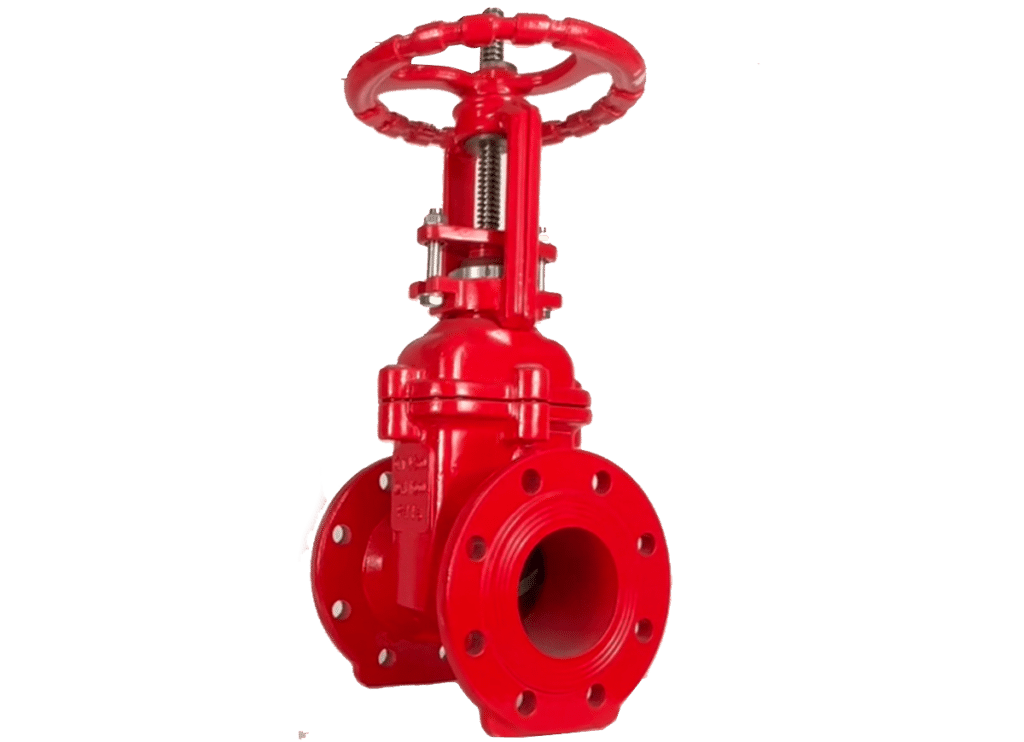
A gate valve is a type of valve that fully opens or fully closes the flow by moving a plate up and down. It’s the most widely used valve for stopping the flow in pipeline systems.
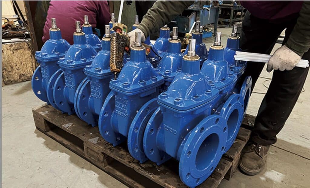
Judberd gate valve
Gate Valve Parts and Design
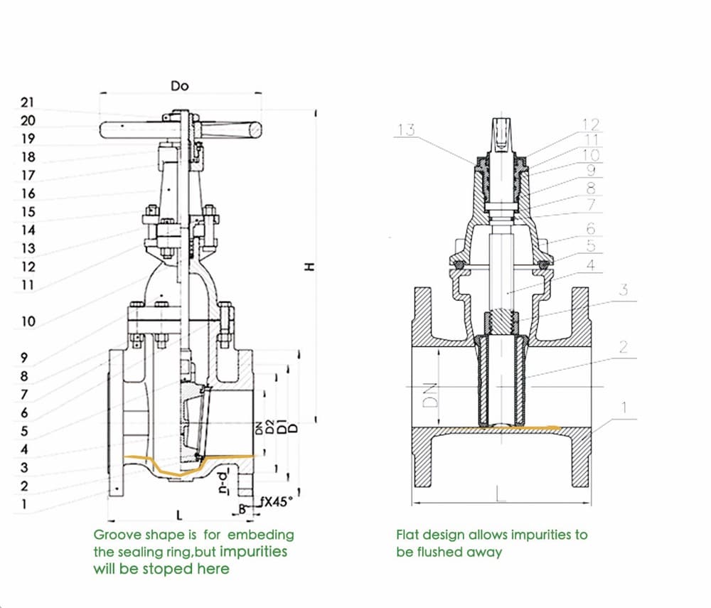
The main parts of a gate valve are the valve body, valve bonnet, stem, gate, and operating mechanism. When you use the operating mechanism (such as a hand wheel , stem nut, worm gear, electric or pneumatic actuator) to operate the valve, the stem (shown as “4” as below diagram) starts to rotate (NRS gate valve) or lift (OS&Y gate valve), causing the gate (shown as “2” as below diagram) to move up or down. When the gate rises, the valve opens. When the gate descends, the valve closes.
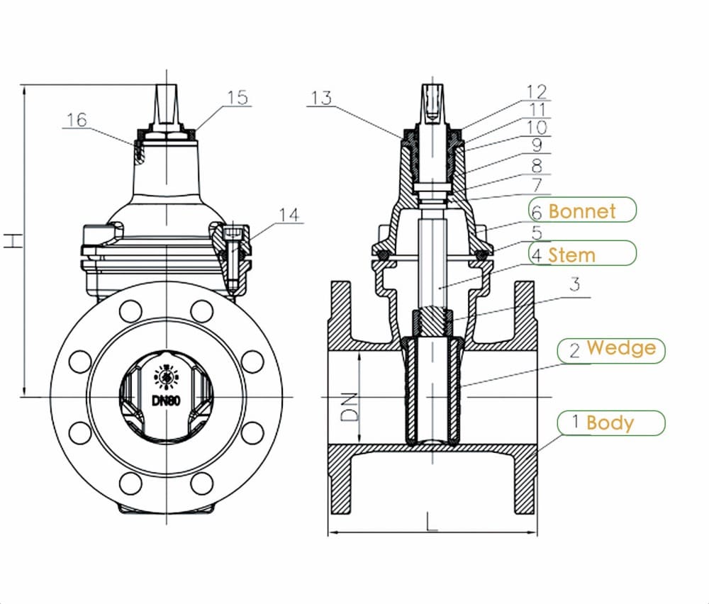
Judberd gate valve drawing
For large gate valves, it’s important to include a bypass valve when necessary. The bypass valve helps prevent excessive pressure that could damage the main valve gate. You can open the bypass valve first to reduce the pressure difference on both sides of the main valve gate
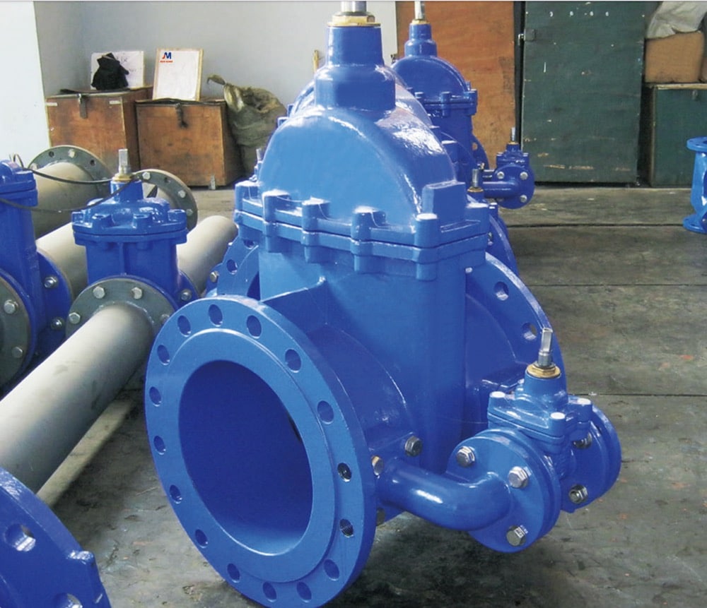
Judberd gate valve
Type of Gate Valves
A gate valve is the most commonly used valve for cutting off flow in pipelines. There are different classifications based on the needs:
1,Based on the different transmission between the valve disc and the stem, it can be divided into non-rising stem (abbreviated as NRS) and rising stem (abbreviated as OS&Y).
NRS gate valves are more widely used compared to OS&Y gate valves. NRS valves are suitable for underground and tight spaces because their stem doesn’t rise. However, since the stem only rotates without rising when opening or closing the valve, you can’t tell the disc’s status from the outside by looking at the stem.
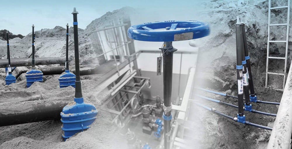
photo from google, for instruction purpose only
In an OS&Y gate valve, the stem rises when you open the valve and descends when you close it. This design isn’t suitable for underground or tight spaces. However, it allows you to visually check the valve’s status by looking at the stem’s position, making it suitable for situations where you need a clear view of the valve’s opening and closing.
Judberd os&y gate valve
2,According to the sealing method, gate valves can be divided into resilient seated and metal seated.
Resilient seated gate valves have a rubber-coated gate, creating a flexible seal between the gate and the valve body. Because rubber can deform elastically, it provides better sealing than hard seals.
Resilient seated gate valves are suitable for media with small volumes of hard impurities. Though small particles may deform the rubber, the flat interior of the valve body allows easy flushing of particles. Once the particles are flushed away, the rubber can return to its original shape.
Resilient seated gate valves are generally used for applications requiring strict sealing, with small volumes of hard impurities, in media that are not harmful to rubber. They are not suitable for pipelines with pressures equal to or greater than PN40.
Metal seated involves embedding metal sealing rings on top of the valve disc and valve body, creating a seal through the compression of these two rings.
Because sealing rings are embedded on top of the valve body, the body is recessed, not flat. Therefore, it is not suitable for situations with hard particles, as they may damage the valve disc during sealing, leading to leaks.
Metal-seated gate valves are generally suitable for pipelines without hard particle impurities, in highly acidic or alkaline, high-temperature, and high-pressure conditions that could harm rubber.
3,According to the design of the valve disc, gate valves can be classified as parallel and wedge types.
In a parallel type gate valve, the sealing surfaces of the valve disc and valve body are parallel, allowing for quick up-and-down movements of the disc. However, parallel types cannot withstand high pressure compared to the wedge type. For example, the knife gate valve uses a parallel type gate.
In a wedge type gate valve, the sealing between the valve disc and valve body is wedge-shaped, providing better sealing performance and the ability to handle higher pressures. Generally, common gate valves use the wedge type design.
Gate Valve Function
Gate valves can be used to shut off gases, oil, water, mud, slag, and other substances. Depending on the substance, gate valves may vary in material, sealing method, and connection type.
For example, for oil applications, carbon steel is commonly chosen with hard sealing, and pressures range from PN10 to PN100. The surface is usually painted.
For water, ductile iron is often used with soft sealing, occasionally with hard sealing, and pressures are generally less than or equal to PN25.
For mud, slag, and similar substances, knife gate valves are typically used, with lower pressure requirements and less strict sealing standards.
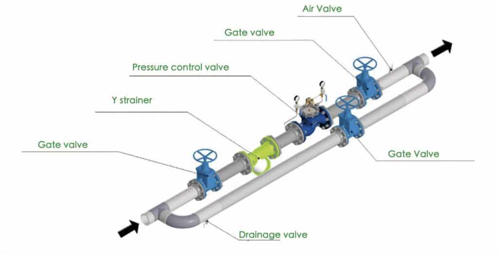
Gate Valve Location and Installation
Gate valves are suitable for pipelines where you need to shut off the flow of substances. They can be installed horizontally or vertically.
Installation steps are as follows:
1,Flanged Gate Valve
1,Align the bolts holes of gate valve with the bolt holes of the connecting pipe components.
2,Install two sets of bolts, nuts, and washers for positioning, but do not tighten them yet.
3,Place a sealing gasket between the two flanges.
4,Tighten the bolts diagonally, applying even force each time and gradually tightening. Avoid overtightening in one go.
2,Socket Gate Valve
1,Clean the interior of the socket ends of gate valve.
2,Place the gasket in the correct position on the socket end.
3,Lubricate the socket end thoroughly with lubricating oil or grease.
4,Insert the spigot end into the socket joint of gate valve with the gasket in place. Since the gasket provides a self-sealing function, pulling the inserted pipe outward will make the gasket seal more tightly.
3,Mechanical Joint Gate Valve
1,Install the PE pipe onto the restrained adaptor.
2,Align the bolt holes of the mechanical joint gate valve with those on the restrained adaptor.
3,Tighten each bolt diagonally, applying even force each time and gradually tightening. Avoid overtightening in one go.
Gate valve operation
Gate valves are commonly operated using handwheels, Stem nut, worm gear, electric actuators, and pneumatic actuators.
Handwheels are typically used for above-ground operations. For underground gate valves, a pipeline well needs to be dug, and an extended rod is added for handwheel operation from above ground.
Stem nut are used for underground operations and can connect to an extended spindle. Above ground, the valve can be operated using either a handwheel or a wrench. An integrated extension spindle with a T-shaped wrench can also be used, reaching directly underground for valve control.
Worm gear are generally used for above-ground operations, especially for large-sized gate valves, reducing the operating torque. Common worm gear types include bevel gear and spur gear. Bevel gear allows side operation on the gate valve, reducing torque while saving space. Spur gear operates in the original position, reducing torque.
Electric and pneumatic actuators control valve opening and closing using electricity or compressed air, mainly for remote operations. Note that for gate valves controlled by electric and pneumatic actuators, the threaded portion of the stem should be reduced from two to one. This is because the power from electric and actuator operations can cause damage to the valve disc and stem if the switch is too fast. Therefore, a single-thread stem is used to avoid speeding up the switch.
Gate Valve Problem and How to Prevent
In the use of gate valves, several common issues can be avoided to extend their lifespan:
1,Wear of O-rings on the stem:
Solution: Design an inverted sealing structure. When the valve is fully open, the gate and the valve cover create a seal. This allows easy replacement of the O-ring without disrupting normal pipeline operation, even under pressure.
2,Stem detachment:
Solution: Mold the stem and dull-press it as one piece. This prevents wear between the stem and the retaining ring, eliminating the risk of detachment and prolonging the valve’s lifespan.
3,Sealing issues between the valve body and cover
Solution: Adopt a T-shaped sealing structure. With increasing water pressure, the sealing ring between the valve body and cover expands, improving the sealing effect.
4,Rubber aging
Solution: Use high-quality rubber. Judberd ensures top-notch rubber quality, from raw material selection to rubber lining, all done in-house. This guarantees an extended valve lifespan.